
HIGHLY INFLAMMABLE!

Here, I've listed a few precautionary measures to take to mind!
HAVE FIRE EXTINGUISHER AND FIRE BLANKET IN YOUR VICINITY
PLACE THE VEHICLE IN A QUARANTINED AREA AND ARRANGE 'NO SMOKING/PETROL FUMES' SIGNS ABOUT THE VEHICLE.
BEFORE ANY WORK IS CARRIED OUT ON THE FUEL SYSTEM, GROUND THE VEHICLE TO EARTH AND MAINTAIN THE GROUND CONNECTION UNTIL THE WORK IS COMPLETED.
DO NOT SMOKE OR CARRY LIGHTED TOBACCO OR OPEN FLAME, SPARKS OF ANY TYPE WHEN WORKING ON OR NEAR ANY FUEL RELATED COMPONENTS.
HIGHLY FLAMMABLE VAPOURS ARE ALWAYS PRESENT AND MAY IGNITE.
THE FUEL SYSTEM REMAINS PRESSURIZED FOR A LONG TIME AFTER THE IGNITION IS SWITCHED OFF. THE FUEL PRESSURE MUST BE RELIEVED BEFORE ATTEMPTING ANY REPAIRS.
AFTER CARRYING OUT REPAIRS, THE FUEL SYSTEM MUST BE CHECKED VISUALLY FOR LEAKS.
THIS PROCEDURE INVOLVES FUEL HANDLING. BE PREPARED FOR FUEL SPILLAGE AT ALL TIMES AND ALWAYS OBSERVE FUEL HANDLING PRECAUTIONS.
IF TAKEN INTERNALLY DO NOT INDUCE VOMITING SEEK IMMEDIATE MEDICAL ATTENTION.
IF FUEL CONTACTS THE EYES, FLUSH THE EYES WITH COLD WATER OR EYEWASH SOLUTION AND SEEK MEDICAL ATTENTION.
WASH HANDS THOROUGHLY AFTER HANDLING, AS PROLONGED CONTACT MAY CAUSE IRRITATION. SHOULD IRRITATION DEVELOP, SEEK MEDICAL ATTENTION.
WHEN RELIEVING COOLING SYSTEM PRESSURE, COVER THE EXPANSION TANK CAP WITH A THICK CLOTH TO PREVENT THE POSSIBILITY OF SCALDING. TURN THE EXPANSION CAP COUNTERCLOCKWISE A QUARTER TURN TO RELIEVE THE COOLING SYSTEM PRESURE, RE-TIGHTEN CAP.
DISCONNECT THE BATTERY GROUND CABLE.
FAILURE TO FOLLOW THESE INSTRUCTIONS MAY RESULT IN PERSONAL INJURY.
NOTE: Very important: Before attempting to remove the intake manifold,
assure yourself that nothing can
fall into the lower intake, some intake valves will be open and things can fall
into the cylinder which will be hard to get out. After removing the intake manifold, use a flash-light to assure
yourself that nothing has fallen in, plug each intake hole tightly with a piece of cloth. After cleaning the intake gasket
surfaces use a vacuum cleaner to suck away remaining debris. This procedure should also be considered when changing the
spark-plugs, so, look first. Not to follow this procedure can result to serious engine damage.
NOTE! Before cranking the engine, turn the crankshaft a few turns per hand (ratchet) to assure yourself that the engine turns free!
NOTE! Do not attempt to clean the throttle body. The Bohr and the throttle plate has a special coating applied during manufacture which should not be removed.
NOTE! When the battery cable has been disconnected and reconnected, some abnormal drive symptoms may occur while the vehicle relearns its adaptive strategy. Have your radio security code at hand.
FILL AND BLEED THE COOLING SYSTEM.
Here, I have modified a cheap ultrasonic cleaner with a bypass switch for permanent and timed activities.
Further, I have built myself an adjustable pulsating frequency unit out of a flasher relay. At the bottom of this page
there is a circuit diagram of an electronic circuitry with an adjustable duty cycle, but first, follow the underlining
procedures.
Connect a compressed air line (max.5bar), set the air pressure
to the maximum allowable fuel pressure, probably 3bar, sport vehicles 5bar.
Connect a power supply that represents the recommended injector valve voltage, without power applied,
remaining fuel in the injector will not be dispersed.
Set already flushed injector valves with power detached, compressed air pressure equivalent to fuel pressure, in a
hot water bath (60-80°C) without any other substances, permissible volume of emerging bubbles per injector valve,
2 with in a 15 second period, if more, clean them. When thoroughly cleaned and with test achieved, install immediately
(corrosion), run engine, visually check for leaks.
Injector valves can only be cleaned when they are open, either through a permanent or a pulsed voltage supply.
Pulsed results in a pump and flush activity that flushes out loosened debris.
Injectors valves also have at their fuel entrance a fine filter, this is the last stop for debris entering the injector, should,
the main fuel filter web internally bust due to the lack of maintenance or other causes, the debris stops here,
filter can be replaced by using a tap to cut a short thread of 1 turn, then pull the tap with the hooked filter. These fine filters
can be cleaned through the ultrasonic bath the same way as the injector nozzle, simply turn then around. Further in this
video you will see the injectors in action, look at each injector squirting pattern, see if there is a conus
like squirting pattern for every injector nozzle channel, here we have four nozzles, so four narrow conus like squirting paths.
Injectors shouldn't squirt sides ways, they should always disperse the fuel in a fine dusty way.
Remember, gasoline is always dangerous not only being very explosive but also as a health risks, for instance
Benzol can be a cause of cancer, being inhaled could cause
hallucinations, dizziness, aggressiveness and impaired judgment. Always keep the lot ventilated!
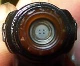
Here, we see four injector channels, while, the 3.0l V6 Jaguar engine has four valves per cylinder, 2 intake (2 injector-channels per valve), 2 exhaust.
This injector comes with a coil resistance of 12 to 16 ohms and a >10 Mega ohm coil insulation resistance.
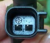
So, here we can see the polarity, of how this injector is connected in the circuitry. This injector is tide to a supply voltage >12v and
is therefore negatively triggered.
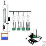
So, here is my illustration of a home brew injector testing system, on the left side
there is the pressure unit, which is a hand pump with an in and outlet valve. This hand pump comes
with a piston diameter of 56mm and a maximum volume of 500ml. By using the formula p=F/A
calculate the needed mass (kg) for the force N (weight here is water 1l=1kg,
1kg x 9,81m/s²= 9.81kg m/s²= 9.81N (1N=1kg*m/s²)) for the wanted pressure of 3 bars. If you don't
have measuring cylinders use something likewise, with a 100g-200g weighing scale with 0.01g tolerances (10euro)
measure the weight of each containment, note its weight, inject fluid to a maximal level,
weigh each containment again, note its weight, subtract the containment weight.
The weight of all fluids should be identical, if not, repeat the
cleaning process again and again. If the cleaning process did not deliver the desired result, there is a big probability that
the internal valve needle spring got weak and the valve stays open to long.
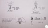
A spray pattern example.

Here's an injector, ignition coil driver. With this simple and powerful driver, you can create very high
voltages when driving ignition coils or drive fuel injector coils at different duty cycles. The principle work scheme of this circuitry
is that it works like a switching power supply. In this case the power distributed is not redistributed
back to the circuit, though, it is regulated through the change of its period and impulse duration which in this case
is contain in specific parameters and therefore separately adjustable. The main point of this circuit is its output-stage
amplification, particularly the power transistor (IGBT). Through the very fast depreciation (500ns) of the primary voltage, there is a high
and wide inductance, not only in the secondary windings but also in its primary, which can get very high when the spark gap
gets longer and longer and then destroys the IGBT (1200V). Therefore the power transistor (IGBT) has to be held in its specific parameters. Its safety
circuitry, here a Varistor (VAR1) which lets the higher than allowed peak voltages (IGBT HEF40106 shut-down about 500ns, 16A permanent power,
27A maximum, 1200V high-voltage proof) starting from 800V to 1100V be bypassed to minus.
How does it work?
The circuit connector X2 is fed with a voltage of +19V to +35V. Over the linear voltage
regulator U1 we get a stabilized voltage of 15 volts, which is the best working parameter for this circiut. With the use of two
CMOS Schmittrigers one of which is an HEF40106 that feeds the driver.
The first stage (IC1A) is a astable multivibrator
which produces a periodic rectangular signal with an adjustable periodic time table of about 6ms to 46ms.
The second stage
is a monostable multivibrator which produces an adjustable impulse of about 120us to 4ms period.
The main purpose
of using a circuit like this is to keep the impulse period on the adjusted level when the frequency changes.
Timers like
the 555 series impulse duration can't be adjusted when the frequency changes.
The rectangular wave signal drives a MOSFET IR211 (IC2).
The MOSFET's purpose is to bring a clear and powerful drive signal to the output IGBT SPG07N120. The IGBT drives the ignition coil, whereby the
coil is connected (X1) to +9V to +24V.
Important!
Experimenting with voltages can be very dangerous, if
you are not inclined with electro-technique than don't experiment with this circuit.
Now you have
completed your circuit and the High-voltage tension wire (4) is gaped to ground.
Start voltage = adjusted to 20V.
Period duration T = adjusted to its maximum.
Impuls duration t = adjusted to its minimum.
Oscilloscope voltage
at R6.
Set spark-gap to about 5mm.
Power voltage = 12V (set laboratory power-supply to max. 2A)
Slowly prolong the Impuls-duration and keep an eye on your Amp-meter.
With an impulse-duration of about 200us a spark should occur.
Now, by (carefully!) adjusting voltage,
period, impulse duration you can get some experience of how this circuit functions.
Note of caution
This driver is so strong, that the inner isolation of an ignition-coil can be
permanently damaged, when the impulse energy is turn to high. Sparks of about 30mm (about 100KV at atmosphere) are achievable,
dependent upon ignition-coil type. Most all ignition-coils die through shot-through insulation either
internal or external and to a lesser extent shorted winding.
When the spark encounters high, hot internal combustion pressure, the spark has to overcome a very high resistance
(pressure, high combustion temperature, mixture lean or rich and some other odds) at its gap with a very high voltage
at a very high speed.
When the encountered resistance (spark-path ionization) is greater than the damaged insulation resistance of the ignition-coil, the very high
voltage will always uses the easiest way to let part or all of its energy off, so a usable spark of about
30KV to 50KV can't be reached when the engine is under high stress. We have combustion pressures of about
10bar to 20bar. Ionizing an arc-path at atmosphere is easier then when it is in a chamber with a
hot compressed fuel mixture in it.
At atmosphere we need about 3.3KV/mm to ionize the spark-gap. A spark-gap in todays modern engines can
be as wide as 1mm - 2mm.
So, we can say that at 10bar combustion pressure and to ionize a spark-gap of 1mm we need about 5x the voltage
at atmosphere.
Than the insulating material, both windings and outer casing rapidly lose their high resistance, (cold 20°C >10GOhm to 50-100MOhm at 80°C)
when temperature rises. So, what do we conclude out of this? Ignition-coils should be checked at their maximum allowable working
temperature (data-sheet). If one or two coils are damaged, change them all, than the customer will comeback after a while
with the same problem.

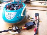
Here's an ultrasonic household cleaner with a custom made injector mount. This kind of cleaner has
only one ultrasonic wave producer, which is directly mounted under the round molded cavity.
This kind of unit will do the job to, though, it will need more time. All injectors have to be bound together
and be placed directly over the ultra sonic unit (see clip).
General Service Information
General Service InformationRear axle
Rear sub-frameFront axle
Lower ball-point joint, Shock absorber bushes, Stabilizer bar links + mountsBrake disc and pads
Engine
Intake Manifold / Ignition Coils / Spark-plugs/ engine-block ventilation (elbow)Injectors
Starter system
Valve clearance, timing-chain, tensioner and glides:
With valve clearance in its tolerance,
there was no need to take the camshafts down, so tensioners and co. have to wait, the good thing is the
tensioner pumps up in 3-4 min. the rattle noise disappears.
Cruise control malfunction, emergency mode
Automatic Transmission 5R55N
Info, tips, Fail Safe ModeStall Speed Test procedure and diagnoses
Valve Body, known issues
Valve Body, Solenoid test procedures
Line Pressure Test
Self made press for pressing down clutch drum springs, checking clutch tolerance without a dial gauge
Chassis
Air ConditioningMiscellaneous repairs
Wind-shield-wiper mechanism:
Time on the lot took its toll, wind-shield-wiper shafts had seized,
uninstalled the mechanism, freed the seized shafts through the use of a good rust loosener, heat, force.
Water in Spark-plug wells 3-2 cylinder:
After days of heavy rain the engine began to misfire with
accounted trouble codes, spark-plug wells were wet, an ionized rusty red path on the ceramic insulator had developed which shorted the
HV ignition spark.
Radio:
Connected the radio controls to the multi-functional steering wheel using
an analog digital converter.