Welcome to

An Automobile Diagnosis Website
General service Information
Repairs and replacements
When service parts are required, it is essential(?) that only Jaguar/Daimler replacements are used.
Attention is drawn to the following points concerning repairs and the fitting of replacements parts.
Safety features embodied in the vehicle maybe impaired if other than genuine parts are fitted. In certain
territories, legislation prohibits the fitting of parts which are not produced to the vehicle manufactures
specifications.
Torque wrench setting figures given must be strictly adhered to.
Disconnecting/connecting the battery
Always stop the engine before disconnecting the battery negative lead and make sure the battery positive lead is
isolated i.e. wrapped in a suitable cloth.
Warning:
RADIO CODE SAVING DEVICES MUST NOT BE USED WHEN CONDUCTING WORK ON AIR BAG OR FUEL SYSTEMS. IT MUST BE NOTED
THAT, WHEN USING THESE DEVICES, THE VEHICLE ELECTRICAL SYSTEM IS STILL ALIVE ALBEIT WITH A REDUCED CURRENT FLOW.
NOTE:
Before disconnecting the battery make sure that the radio receiver/cassette player/mini disc and compact disc
player key codes are known and, that no data is required from the engine control module (ECM) as battery
disconnection will erase any fault code and idle/drive values held in Keep Alive Memory (KAM). It is not necessary
to disconnect or remove electronic control modules.
Always disconnect the battery before commencing repair operations which require:
The vehicle to be jacked up
Work on the engine
Work underneath the vehicle
Arc welding
Alternatively a Radio Code Saver maybe used. With the battery disconnected, a Radio Code Saver will allow sufficient
current to pass to maintain the security codes, clock and supply the door operated interior lights while isolating the
battery in the event of a short circuit.
Reconnecting the battery
Warning:
IF THE BATTERY HAS BEEN ON BENCH CHARGE THE CELLS MAYBE GIVING OFF EXPLOSIVE HYDROGEN GAS. AVOID CREATING SPARKS,
AND IF IN DOUBT COVER THE VENT PLUGS OR COVERS WITH A DAMP CLOTH.
Always make sure that all electrical systems are switched OFF before reconnecting the battery to avoid causing sparks
or damage to sensitive electrical equipment.
Always reconnect the battery positive lead first and the negative last, ensuring that there is a good electrical
contact and the battery terminals are secure.
Restart the clock (where fitted) and set the correct time.
Re-enter the radio ext. security codes.
Following re-connection of the battery, the engine should be allowed to idle until it reached normal operating
temperature as the stored idle and drive values contained within the ECM have been lost.
Allow the vehicle to idle for a further three minutes.
Drive the vehicle at constant speeds of approximately 48 km/h (40mph), 80 km/h (50mph), 96 km/h (60mph) and
112 km/h (70mph) for three minutes each.
This may cause a drive-ability concern if the procedure is not carried out. This will allow the ECM to relearn its
idle values.
Connecting a Slave Battery Using Jump Leads
Warning:
IF THE SLAVE BATTERY HAS RECENTLY BEEN CHARGED AND IS GASSING, COVER THE VENT PLUGS OR COVERS WITH A
DAMP CLOTH TO REDUCE THE RISK OF EXPLOSION SHOULD ARCING OCCUR WHEN CONNECTING THE JUMP LEADS.
CAUTION:
A flat battery condition may have been caused by an electrical short circuit. If this condition exists there will
be an apparently live circuit on the vehicle even when all normal circuits are switched off. This can cause arcing
when jump leads are connected.
CAUTION:
Whilst it is not recommended that the vehicle is jump started, it is recognized that this may occasionally be the
practical way to mobilize a vehicle. In such an instance the discharged battery must be recharged immediately
after jump starting to avoid permanent damage to the battery or to the generator. Generators are not designed to
charge deep discharged batteries.
Always make sure that the jump leads are adequate for the task. Heavy duty cables must be used.
Always make sure that the slave battery is of the same voltage as the vehicle battery. The batteries must be
connected in parallel.
Always make sure that switch-able electric circuits are switched off before connecting jump leads. This
reduces the risks of sparks occurring when the final connection is made.
Warning:
MAKE SURE THAT THE ENDS OF THE JUMP LEADS DO NOT TOUCH EACH OTHER OR GROUND AGAINST THE VEHICLE BODY AT ANYTIME
WHILE THE LEADS ARE ATTACHED TO THE BATTERY. A FULLY CHARGED BATTERY, IF SHORTED THROUGH JUMP LEADS, CAN DISCHARGE
AT A RATE WELL ABOVE 1000 AMPS CAUSING VIOLENT ARCING AND VERY RAPID HEATING OF THE JUMP LEADS AND TERMINALS, AND
CAN EVEN CAUSE THE BATTERY TO EXPLODE.
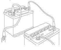
Always connect the jump leads in the following sequence.
Slave battery positive first then vehicle battery positive.
Slave battery negative next and then vehicle ground at least, 300mm (12in) from the battery terminal e.g.
engine lifting bracket.
Always reduce the engine speed to idle before disconnecting the jump leads.
Before removing the jump leads from the vehicle that had the discharged battery, switch on the heater blower (high)
or the heated rear screen, to reduce the voltage peak when the leads are removed.
Always disconnect the jump leads in the reverse order to the connecting sequence and take great care not to short
the ends of the leads.
Do not rely on the generator to restore a discharged battery. For a generator to recharge a battery, it would take an
excess of 8 hours continuous driving with no additional loads placed on the battery.
Component Cleaning
To prevent the ingress of dirt, accumulations of loose dirt and greasy deposits should be removed before disconnecting
or dismantling components or assemblies.
Components should be thoroughly cleaned before inspection prior to reassembly.
Cleaning Methods:
Dry cleaning
Removal of loose dirt with soft or wire brushes
Scraping dirt off with a piece of metal or wood
Wiping off with a rag.
Caution:
Compressed air is sometimes wet so use with caution, especially on hydraulic systems.
Blowing dirt off with compressed air. (Eye protection should be worn when using this method).
Removal of dry dust using equipment. This method should always be used to remove friction lining
material dust (asbestos, nano particles).
Steam cleaning
Calibrations of Essential Measuring Equipment
Warning:
FAILURE TO COMPLY MAY RESULT IN PERSONAL INJURY OR DAMAGE TO COMPONENTS.
It is of fundamental importance that certain essential equipment e.g. torque wrenches, multimeter, exhaust gas
analyser, rolling roads etc., are regularly calibrated in accordance with the manufactures instructions.
Use of Control Modules
Control modules may only be used on the vehicle to witch they were originally fitted. Do not attempt
to use or test a control module on any-other vehicle. (Software version differences, may lead to short circuits)
Functional Test
On completion of a maintenance procedure, a thorough test should be carried out, to make sure that the relevant
vehicle systems are working correctly.
Preparation
Before, dis-assembly, clean the surrounding area as thoroughly as possible. When components have been removed,
blank off any exposed opening using grease-proof paper and masking tape. Immediately seal fuel, oil and
hydraulic lines separated, using plastic caps or plugs, to prevent loss of fluid and the entry of dirt. Close
the open ends of oil-ways, exposed by component removal, with tapered hardwood plus or readily visible plastic plugs.
Immediately a component is removed, place a suitable container, use a separate container for each component and its
associated parts. Before dismantling a component, clean it thoroughly with a recommended cleaning agent, check that
the agent will not damage any of the materials within the components. Clean the bench and obtain marking materials,
labels, containers and locking wire before dismantling a component.
Dismantling
Observe scrupulous cleanliness when dismantling, particularly when parts of the brake, fuel or hydraulic
systems are be worked on. A particle of dirt or a fragment of cloth could cause a dangerous malfunction if
trapped in these systems. Clean all tapped holes, crevices, oil-ways and fluid passages with compressed air.
Make sure that any O-rings used for sealing are correctly refitted or renewed if disturbed. Mark mating parts
to make sure that they are replaced as dismantled. Whenever possible use marking materials which avoid the possibility
of causing distortion or the initiation of cracks, which could occur if a centre punch or scriber were used.
Wire together mating parts where necessary to prevent accidental interchange (e.g. roller bearing components).
Tie labels to all parts to be renewed and to parts requiring further inspection before being passed for
reassembly. Place labelled parts and other parts for rebuild in separate container. Do not discard a part which
is due for renewal until it has been compared with the new part, to make sure that the correct part has been obtained.
Inspection
Before inspecting a component for wear or performing a dimensional check, make sure that it is absolutely clean,
a slight smear of grease can conceal an incipient failure. When a component is to be checked dimensionally against
figures quoted for it, use the correct equipment (surface plates, micrometers, dial gauges etc.) in serviceable condition.
The use of makeshift can be dangerous. Reject a component if its dimensions are outside the limits quoted, or if damage
is apparent. A part maybe refitted it its critical dimension is exactly to the limit size and it is otherwise satisfactory.
Use Plastigauge 12 Type PG-1 for checking bearing surface clearance, e.g. big end bearing shell to crank journal.
Instructions for use of Plastigauge and a scale giving bearing clearances in steps of 0.0025mm (0.0001in) are
supplied with the package.
On-Board Diagnostics (OBD)
This vehicle uses programmed electronic control systems to provide engine management and emission regulation,
automatic transmission and anti-lock braking control. These control systems are integral with the On-Board
Diagnostics (OBD) facility which is used in conjunction with either the Jaguar approved diagnostic or the more
restricted scan tools.
General Service Information
General Service InformationRear axle
Rear sub-frameFront axle
Lower ball-point joint, Shock absorber bushes, Stabilizer bar links + mountsBrake disc and pads
Engine
Intake Manifold / Ignition Coils / Spark-plugs/ engine-block ventilation (elbow)Injectors
Starter system
Valve clearance, timing-chain, tensioner and glides:
With valve clearance in its tolerance,
there was no need to take the camshafts down, so tensioners and co. have to wait, the good thing is the
tensioner pumps up in 3-4 min. the rattle noise disappears.
Cruise control malfunction, emergency mode
Automatic Transmission 5R55N
Info, tips, Fail Safe ModeStall Speed Test procedure and diagnoses
Valve Body, known issues
Valve Body, Solenoid test procedures
Line Pressure Test
Self made press for pressing down clutch drum springs, checking clutch tolerance without a dial gauge
Chassis
Air ConditioningMiscellaneous repairs
Wind-shield-wiper mechanism:
Time on the lot took its toll, wind-shield-wiper shafts had seized,
uninstalled the mechanism, freed the seized shafts through the use of a good rust loosener, heat, force.
Water in Spark-plug wells 3-2 cylinder:
After days of heavy rain the engine began to misfire with
accounted trouble codes, spark-plug wells were wet, an ionized rusty red path on the ceramic insulator had developed which shorted the
HV ignition spark.
Radio:
Connected the radio controls to the multi-functional steering wheel using
an analog digital converter.