
Take care, be cautious, you're working with
High Voltage!

Here, I've listed a few precautionary measure's to take, when working with the ignition system and what kind of tools I used.
Tip: Some modern Ignition-coils
need the use of a special lever-tool to loosen the coil directly vertical from their mounted position, otherwise
the coil could break, but not here.
Further, I used an OBDII scantool (Chinese ELM327 interface + Scanmaster).
This millennium Jaguar model has about 120 OBD2 Power-train DTCs, that can be read, when flagged. Manufacturer DTC's concerning Body, Chassis and Network are unaccessible.
I've also purchased
a JTIS DVD, you'll need one, its a must, all items were bought through yabE. Further, the Internet has a large S-type knowledge base for
possible Q+A.
Use HV-tension pliers when working with a live system and Multimeter, check light.
Possible OBDII Ignition-coil DTC's (Diagnostic Trouble Code):
P0350 to P0358
Note!: Jag's manufacture DTC's will only be readable if they are OBD2 protocol compliant, this means here, they are not, no Body, Chassis, nor Network codes.
Otherwise use software from Gendan Automotive Products, AutoEngenuity, professional software or readers.
Use your JTIS's DTC's Powertrain summary, note, if you have a DTC P1000 stored in the PCM's memory, do all 7 Drive-cycles as described! (drive-cycle tests not complete), after completion, readout PCM memory for possible DTC's and save, delete DTC's, repeat
Drive-cycle test again. If no DTC is stored do nothing, if a TDC, go to the JTIS's wiring diagram, search for the troubled unit, check the unit's
connections (corrosion, wire connector contact weakness (tighten or bypass connection, use electronic spray), wire-harness (damaged, check for short to +-, a wet-short, changes the capacitance of the wire,
than water has a very high dialectical value and would change the signal at it's ends, do a frequency gen. + Scope test). With the use of a Multimeter
or Scope and with the JTIS's trouble shooting documentation do a trouble check.
NOTE: Very important! Before attempting to remove the intake manifold, assure yourself that nothing so small whatever (exp. lost small screws, nuts, washers, gasket rests and so on) can fall into the lower intake, than, some intake valves will be open and things can fall directly into the cylinder. After removing the intake manifold use a flash-light to assure yourself that nothing has fallen in, plug each intake hole tightly with a piece of cloth. After cleaning the intake gasket surfaces use a vacuum cleaner to suck away remaining debris. The same procedure should be applied when changing the spark-plugs, look down into the spark-plug wells. Not to follow this procedure can relate to serious damage to the engine.
NOTE: When the battery cable has been disconnected and reconnected, some abnormal drive symptoms may occur while the vehicle relearns its adaptive strategy. Have your radio security code at hand.
Tip: Don't do any cleaning with pressured water on electrical components (seals get bad with the years). Car engine compartments or other sensitive areas such as A/C connection lines, condenser, shouldn't be cleaned with high-pressure (water, steam) cleaners. This type of cleaning, presses water into places were it shouldn't be, for instance, directly into the A/C system, in wheel bearings, or between wheel-hub and brake disk (rust pressing your brake disk that it wobbles), in spark-plug wells (misfires), in sealed electrical connectors, in wiring harnesses (older ones that are cracky) were it can hardly escape, therefore causing micro-amp shorts that set malfunction indicators (MIL, PCM, ABS, ...), electro-corrosion, unusual behaviour of electric components.
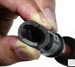
Here's one of the big problems, a fried to the spark-plug, riped apart, cracky, hardened booty that can't
insulate anymore. Though, under normal driving conditions an HV at about 15KV a boot like this one could still work, but an engine in
extreme acceleration or in stress mode, where the HV can reach 40KV, the HV will definitely take this way to unload
itself. Tip, install new boots, use a little bit of spark-plug grease to lubricate, stop the boot from frying itself to the spark-plug
ceramic and further insulating the gape between the boot and the ceramic insulator of the spark-plug against
a creeping HV.
Spark-plug: For (2000) Jaguar s-type V6
Use a recommended spark-plug with a long changing interval. Check that the new spark-plug
fits snugly into the ignition-coil connections (boot, HV connector). Check the new spark-plug that it hasn't been damaged,
especially bent electrodes or a cracked ceramic insulator (don't let them fall!). Use a light coat of recommended lubricant HT nickel anti-seize F6AZ-9L494-AA (ESE-M12A4-A)
for the spark-plug thread, if your not using this specification you could be changing the spark-plug's heat dissipation value
(insulating the spark-plug) to the cylinder head and causing the spark-plug to overheat (preignition of the fuel-mixture, overheating the piston top (melt through))
and therefor cause engine damage.
Tighten spark-plugs to recommended torque 15Nm. (Tightening them freehand with more than 50Nm will tear them off!)
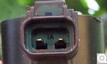
The ignition-coil's Pin 2 is tide to the supply voltage >12v and Pin 1 is therefore negatively triggered through the PCM. To check if each coil gets its trigger (ground-signal), use a test-lamp across its terminals and crack engine, test-lamp should go on and off, before doing this however, you should depressurize your fuel system and have let your engine run dry thoroughly! Cover the manifold intakes and don't let anything fall inside! First check if all coils have their deserved voltage supply, +10.5V or more and that their resistances lay in their parameters, then do the above. These coils have a very low primary resistance, so, they'll suck a lot of power for a few milli-seconds. (10-20amps). If there is no pulsation (test-lamp doesn't glow at all), check the cable and cable harness connections (corrosion (voltage drop), open circuit) to the PCM. If the test-lamp always glows, pin 1 is being grounded, shorted to the chassis or the PCM's ignition transistors have a short. All coil tests should show the same illumination, if not, we have a voltage drop somewhere in the lines, plus cable to pin 2 or minus pin 1 to the PCM. The best way to check a cable harness and its connections is through a voltage drop test. I'am going to explain that here, may be somewhere else.

Note of caution again!
If you are using the ignition-coil and injector driver, the out going signal can be very strong, so, that the inner isolation of an ignition-coil can be
permanently damaged, when the impulse energy is turn to high. Sparks of about 30mm (about 40KV at atmosphere) are achievable,
depends upon what kind of ignition-coil is used. Most all ignition-coils die through shot-through insulation either
internal or external (atmosphere leaks through), to a lesser extent shorted windings.
When the spark encounters high, hot internal combustion pressure, the spark has to overcome a very high resistance
(pressure, high combustion temperature, mixture lean or rich and some other odds) at its gap with a very high voltage
at a very high speed.
When the encountered resistance is higher than the insulation resistance of a damaged ignition-coil, the very high
voltage always uses the easiest way to let part or all of its energy off, so a usable spark of about
30KV to 50KV can't be reached when the engine is under high stress. We have combustion pressures of about
10bar to 20bar. Ionizing an arc-path at atmosphere is easier then when it is in a chamber with a
hot compressed fuel mixture in it.
At atmosphere we need about 3.3KV/mm to ionize the spark-gap. A spark-gap in today’s modern engines can
be as wide as 1mm - 2mm.
So, we can say that at 10bar combustion pressure and to ionize a spark-gap of 1mm we need about 5x the voltage
at atmosphere which is 16.5KV.
Than the insulating material, both windings and outer casing rapidly lose their high resistance, (cold 20°C >10GOhm to 50-100MOhm at 80°C)
when temperature rises. So, what do we conclude out of this? Ignition-coils should be checked at their maximum allowable working
temperature (data-sheet).
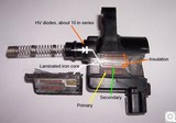
Here's my ignition-coil (EEE03A, XW4U-12A366-AC)
Primary: 0.5 - 1ohm
Secondary: Resistance not measurable due to HV diodes, though, HV diodes can be tested (blocking direction test), adjust your multimeter to +20V,
connect multimeter com lead to your car battery minus, connect multimeter plus lead to ignition-coil spark-plug connector
and one of the primary connections to battery plus. Multimeter should read
no voltage. If you have a voltage indication, the diode has a short circuit.
Reverse the connections on the ignition-coil (foreword direction test), a battery voltage of (minus X multiples of forward voltage drop) should readable.
If not the circuit is open (diode or winding)
A short tutorial: When the ignition-spark encounters high, hot internal combustion pressure, the spark has to overcome a very high resistance
(pressure, high combustion temperature, mixture lean or rich and some other odds too) at its gap with a very high voltage
at a very high speed, charge and discharge about 5ms.
When the encountered resistance (ionization-path) is higher than the insulation resistance of a damaged ignition-coil
(atmosphere leaks through the old cracky damaged resin insulation of the secondary wire or wet and damp spark-plug holes),
the very high voltage will always use the easiest way to unload part or all of its energy, so a usable
spark of about 30KV to 40KV can't be reached when the engine is under high stress. We have combustion
pressures of about 10bar to 20bar. Ionizing an arc-path at atmosphere is easier as when it is in a
chamber with a hot compressed fuel mixture in it.
At atmosphere we need about 3.3KV/mm to ionize the spark-gap. A spark-gap in today’s modern engines can
be as wide as 1mm - 2mm.
So, we can say that at 10bar combustion pressure and to ionize a spark-gap of 1mm we need about 5x the voltage
at atmosphere which is 16.5KV.
Than the insulating material, both windings and outer casing rapidly lose their high resistance, (cold 20°C >10GOhm to 50-100MOhm at 80°C)
when temperature rises. So, what do we conclude out of this? Ignition-coils should be checked at their maximum allowable working
temperature (data-sheet).
General Service Information
General Service InformationRear axle
Rear sub-frameFront axle
Lower ball-point joint, Shock absorber bushes, Stabilizer bar links + mountsBrake disc and pads
Engine
Intake Manifold / Ignition Coils / Spark-plugs/ engine-block ventilation (elbow)Injectors
Starter system
Valve clearance, timing-chain, tensioner and glides:
With valve clearance in its tolerance,
there was no need to take the camshafts down, so tensioners and co. have to wait, the good thing is the
tensioner pumps up in 3-4 min. the rattle noise disappears.
Cruise control malfunction, emergency mode
Automatic Transmission 5R55N
Info, tips, Fail Safe ModeStall Speed Test procedure and diagnoses
Valve Body, known issues
Valve Body, Solenoid test procedures
Line Pressure Test
Self made press for pressing down clutch drum springs, checking clutch tolerance without a dial gauge
Chassis
Air ConditioningMiscellaneous repairs
Wind-shield-wiper mechanism:
Time on the lot took its toll, wind-shield-wiper shafts had seized,
uninstalled the mechanism, freed the seized shafts through the use of a good rust loosener, heat, force.
Water in Spark-plug wells 3-2 cylinder:
After days of heavy rain the engine began to misfire with
accounted trouble codes, spark-plug wells were wet, an ionized rusty red path on the ceramic insulator had developed which shorted the
HV ignition spark.
Radio:
Connected the radio controls to the multi-functional steering wheel using
an analog digital converter.