Welcome to

An Automobile Diagnosis Website
5R55N valve bodies known issues
A line pressure test indicated that line pressure is low. Starting with the known issues (Visual Inspection) and
hopefully, there isn't any burnt clutch, band lining residues, fine metal filings (hard chrome) from a
worn sprag (OWC) or bearing in the AT's oil pan, this would mean the transmission needs a complete overhaul!
Low pressure, band servos and clutch pistons cannot transmit enough force to hold drums and clutches (gears)
firmly, slippage with resulting friction burn their linings.
Note: Worn-out valves or servo bore holes are not a low mileage problem, though wrongly made valve springs can.
As time, mileage a hundred thousand more, the day to day daily city activity shifting gears up and
down take there toll on the valve body where some valves are more active than others.
The PCM(EMC) on its part can through its adaptive strategy compensate for some
wear in the valve body, though at one point the VFS solenoids will reach their end positions,
this is then the point where DTCs are flagged, like gear ratio codes or even simple slippage is felt.
Attention, often the solenoid or the servo pin bore is blamed for the problem, but actually the VFS modulator valves cannot supply enough pressure due to excessive wear (leakage). Check valve body (valve 3,6,10,14,16) and bores (best WAT, though here visually) before removing transmission and servicing the servo bore.
Note: The 5R55N/S/W AT are prone to foaming the ATF in the sump from the valve bodies excess exhaust and valve wear.
This results in fluid out the AT's ventilation vent and improper fill indications.
(a) Permanent line pressure loss through excess exhaust valve wear which is now foaming up the ATF.
(b) Intake of foamed ATF.
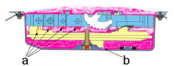
Check ATF consistency, if foaming of the ATF had occurred it would be pink coloured and not clear dark red!
Visual inspection:
Visually inspect spool and bore (pos. 3 (also called PCA or VS1), 6 (TCC modulator), 10 (also called PCB or VS2),
14 (Rev. Mod. Valve, controls direct clutch feed), 16 (Main regulator)) for shinning aluminium surfaces or worn off anodized aluminium.
These tend to wear first due to their busyness.
Info and Tips
Work with utter cleanness (tolerances under .002in), use no fussing materials and no sealant!
Worn-out aluminium or anodized aluminium spools, bores can only be serviced through an oversized valve kit.
Disconnect the battery ground cable, before service. Don't forget to inspect
the grounds at the battery, the PCM, and clean the mass airflow sensor.
Check for any newly made changes (connections) to the electrical circuitry, or for not approved (EMC) radio, cd/dvd players
etc., these items can cause transmission problems.
Check AT harness for damages and bad connections.
The valve springs are subject to breakage, bending or fatigue failure. Broken portions of the spring
can cause the associated valve to stick in either the fully applied or release position. A fatigued
spring will not have enough force to fully stoke the valve to the released position.
Installing the Valve Body:
Fill valve body, solenoid body with ATF, pull ATF under vacuum into solenoid valves, to avert
erratic line pressure and prolonged shifting problems until air pockets have been flushed out, if
this doesn't work run vehicle until hot, let it cool down, then do a road test. Let system relearn its
adaptive strategy this comes with firm, delayed, early, erratic shifting, no up shift without lifting throttle,
2-3 flair 3-4 and 4-5 ok, 1-2 shift late and harsh, 2-3 flair and on time), do a Comprehensive Component Monitor Transmission Drive Cycle, read out
codes. Learning process can take hours.
Check all 3 ball locations when servicing the valve body and replace these with Viton balls
(2 balls and one limit valve)!
Install the two valve body alignment dowels into the transmission casing, align with
valve body (Pos.16,17)!! (wurp, uneven pressure on gasket)
Install the pre-assembled valve body and spacer plate.
CAUTION!
Ensure that the manual valve (Pos.18) is engaged on the inside detent lever properly!
There are different lengths of valve body bolts.
Install all bolts finger tight only at this time!
Install the 27mm length bolt (Pos.15).
Install the 45mm length bolt (Pos.16).
Install the remaining 18, 40mm length bolt.
Install the detent spring assembly (pos.19), 30mm length bolt.
Next, finger tighten only!
Install the pre-checked solenoid body assembly onto transmission.
CAUTION!
Use a drip of ATF on solenoid body connector O-rings help prevent
damage.
Install pre-assembled reverse servo assembly onto spacer plate.
Use a small torque wrench!! (wurp, uneven pressure on gasket)
Torque all of the valve body bolts to 10Nm (89in.lb), beginning in the centre and working
outward in a circular motion. (Do the reciprocal when dismantling, go circular inward)
Torque all of the solenoid body bolts to 8Nm (71in.lb), using a crisscross pattern (inward to outwards).
(Do the reciprocal when dismantling, go criss-cross inwards)
Torque all of the reverse servo bolts to 10Nm (89in.lb), using a crisscross pattern.
(Do the reciprocal when dismantling, criss-cross)
Install new filter seals (drip of ATF) on new filter, torque filter bolts to 10Nm (89in.lb).
Note: The bottom pan gasket is reusable, clean and inspect the gasket for damage, and
if it is not damaged, it may be re-used.
Torque the bottom pan assembly (16 bolts) starting in the middle, going outwards in a crisscross pattern
with 11Nm (8ft.lb.).
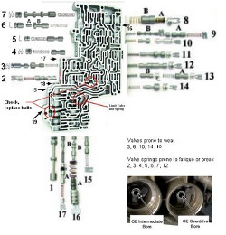
Known issues with valve springs
3, PCA, Modulator Spring, line pressure concerns, poor line rise, low intermediate clutch pressure, poor 2-3 shift, delayed engagements in forward/reverse.
4, Forward Engagement Control Spring, Delay engagements, burned forward clutch, slipping or loss of gears.
5, TCC Back Pressure Spring, harsh torque converter clutch apply, low line pressure, excess slip,
converter overheat (burn-up) or apply complaints, delayed engagements.
6(B), TCC (Torque converter clutch) Modulator spring, harsh torque converter clutch apply, slip on apply, excess TCC slip, Codes 741, 1783, transmission over temperature
6(A), Plunger Valve kit, high TCC slip RPM at increasing load, slip codes, elevated fluid temperature.
7, TCC Control Spring, TCC cycling, excess TCC slip, Code 741, TCC lining coming off, burned converter, engine stall, no TCC release.
10, PCB, line pressure concerns, delayed engagements in forward/reserve.
12, 4-3 Pre-Stroke Spring, (No 4th or 5th gear), failure codes 734 and/or 735, solenoid C code.
13, Delay or loss of reverse, burned direct clutch.
14, delayed reverse engagement, loss of 4th or 5th gear.
16, delayed engagements, soft shifts, high line pressure in reverse.
Other known issues:
Bell Housing or Pump Cover Bushing
Repeat front seal leakage, worn converter hub, worn pump bushing. Excessive hub-to-bushing clearance and soft
bushing material.
Severe pin bore wear (Overdrive, Intermediate servo)
Gear 1-2, 2-3, 4-5 Flares, band lining failure, code 732, 733, 735, gear loss, loss of OD and intermediate servo
control. Severe wear of the case at the servo apply pin bore due to continuous pin oscillation can result in burned
clutches, shift complaints especially delayed reverse, and destroyed cases. Overdrive and intermediate Servo Pin Bore Sleeve kit available.
A damaged intermediate sprag will cause a bind in 3rd and 4th or no 3rd or 4th.
Solenoid body (5R55N 2000-2002) Art-nr.XW4Z-7G391-AE
Solenoid failure, the plastic block covering the solenoid circuit board rubs through solenoid wire strips.
Multiple failure codes may set when this happens.
Valve Body Separator Plate Art-nr.XW4Z-7Z490-AB
No Fourth Gear and No Fifth Gear:
The 4-3 pre-stroke intermediate band control valve spring may break. Many springs were machined incorrectly.
May set failure code PO795 (Pressure Control Solenoid C circuit failure or shorted)
No / or slow engagement concerns, low line pressure, no movement until RPM increased, pump noise,
(Flow Control Valve). The Flow Control Valve is used to help control the volume output of the pump.
The pump flow control canister and plunger valve wear, allowing the plunger valve to stick open and/or
leakage to occur. The canister o-ring relaxes and pressure bleeds past it.
Thermal Bypass Valve, this problem may cause an intermittent lockup failure code PO741
Metal in the Pan, broken Snap Ring, there may be no particular symptom other than metal the pan.
General Service Information
General Service InformationRear axle
Rear sub-frameFront axle
Lower ball-point joint, Shock absorber bushes, Stabilizer bar links + mountsBrake disc and pads
Engine
Intake Manifold / Ignition Coils / Spark-plugs/ engine-block ventilation (elbow)Injectors
Starter system
Valve clearance, timing-chain, tensioner and glides:
With valve clearance in its tolerance,
there was no need to take the camshafts down, so tensioners and co. have to wait, the good thing is the
tensioner pumps up in 3-4 min. the rattle noise disappears.
Cruise control malfunction, emergency mode
Automatic Transmission 5R55N
Info, tips, Fail Safe ModeStall Speed Test procedure and diagnoses
Valve Body, known issues
Valve Body, Solenoid test procedures
Line Pressure Test
Self made press for pressing down clutch drum springs, checking clutch tolerance without a dial gauge
Chassis
Air ConditioningMiscellaneous repairs
Wind-shield-wiper mechanism:
Time on the lot took its toll, wind-shield-wiper shafts had seized,
uninstalled the mechanism, freed the seized shafts through the use of a good rust loosener, heat, force.
Water in Spark-plug wells 3-2 cylinder:
After days of heavy rain the engine began to misfire with
accounted trouble codes, spark-plug wells were wet, an ionized rusty red path on the ceramic insulator had developed which shorted the
HV ignition spark.
Radio:
Connected the radio controls to the multi-functional steering wheel using
an analog digital converter.